wirelessly programmable digital pace clock with a large format LED display and Android smartphone control and programming:
This
original design achieves the functionality of commercailly available pace clocks but with an
intuitive user interface that goes beyond anything that is available in the current marketplace, all at a
small fraction of the cost.
The clock runs from an
Atmel ATmega32A microcontroller and a host of peripheral integrated circuits with a
Bluetooth connection to an original Android smartphone application to configure
swimming workouts, timing intervals, and
real-time wireless control of the clock's features.

The finished product.

The designers.
A Background on Swim Training and Pace Clocks
A pace clock is a large format clock used to time intervals in athletic training, most commonly in swimming or track. Modern pace clocks are large format 4-digit LED displays, with either a grid or 7-segment layout. Swimming workouts are typically organized in advance of a swim practice and include a series of different strokes and drills at various speeds and of various distances. The interval timing can be done with a single count-up clock display, requiring the swimmers and coaches to calculate the appropriate start times and estimate their pace mentally by following a clock. Alternatively, as many proactive collegiate swim coaches do, the day’s or week’s workouts may be programmed into a programmable pace clock to automatically time the swimmers’ sets. This means, for example, that the clock would either count up-to or down-from the interval time (eg. 1 minute and 20 seconds) and then move on to the next interval. This improves workout efficiency by ensuring that the swimmers start the next set on time, and that they receive accurate feedback about their performance and pacing.
An item within a workout will convey to the swimmer (usually in this order): the number of repetitions, the distance, the stroke with optional comments, and an interval. For example, a swimmer might see the following item in a day’s workout:
|
10x 100 Fly (50 Drill/50 Swim) on 1:50 |
This indicates the swimmer must swim 100 yards (or meters, depending on the pool) of the butterfly stroke 10 times, on an interval of 1 minute and 50 seconds, with the first half of each 100 being a butterfly drill and the second half being the standard, full stroke. A pace clock makes this timing possible, and a programmable pace clock makes it easier by counting up to 1:50 (which allows swimmers to see their pace as they finish each 100) or down from 1:50 (which allows swimmers to quickly see how much time remains before they must start the next 100 fly).
Swimming workouts are structured with repetition, loops, and variable intervals, basically a series of the above items that may appear as the repetends of loops. Loops may also appear in the repetends of loops. There are thousands of workouts which can be found online for further clarification.
Pace clocks are expensive and can be cumbersome to use for those not willing to learn their operation and programming method. One of the leading companies selling pace clocks is Colorado Time Systems. A wirelessly programmable pace clock such as the one we have designed and built costs roughly $900-$1400, not including the programmer which costs $440 and is required for programmable workouts. There are additional features on these systems which we did not intend to implement. These may account for some of the difference in expected price between our design ($75 maximum) and the $1k-$2k commercial systems. These differences include battery operation, multiple screen-controlling with a single ($440) controller, and standard interfacing with a much larger product line, including race-accurate timing pads for competition. Many swim teams, particularly in summer swim leagues, cannot afford such elaborate timing systems and cannot justify a fully integrated race timing solution since they rent time at public pools and use rather low-tech timing solutions for races: parents equipped with stopwatches.
"This would be extremely beneficial to competitive swimming at all levels: 'age-group' to collegiate!"
Christaina DiMaria, Cornell Swim Team Captain
High Level Design
Overview
Our project brings together a wide range of hardware and software design experience: from bit level inter-chip communication to processing our compact, original instruction set, to managing user interactions wirelessly in real time, to designing an intuitive user interface for configuring and interacting with the pace clock on an Android smartphone.
Standards
A variety of standards are used to implement communication between peripheral devices, and we use a large fraction of the peripherals available on the ATmega microcontroller. Communicating with the LED drivers is achieved using the SPI interface and a host of other connections required by the TLC5940 devices. These LED drivers are complicated and capable of 12-bit PWM current sinking using an external clock, as well as 6-bit dot-correction tables with persistent and SRAM storage registers. As a result, there is a lot of data formatting and transmitting required to get them to function, even if we only need DC illumination. Communication with a real-time clocking chip uses the I2C/TWI standard (I2C is a proprietary name owned by NXP); the chip itself has many configuration and data registers that can be read and written to perform clock and calendar timing operations. We wrote drivers with simple interfacing functions for both the LED drivers and the clocking chip. Our software uses Peter Fleury's open source I2C/TWI library, available from his website referenced at the bottom of this page. Communication with the radio module uses the microcontroller's onboard USART peripheral unit (asynchronously, so the 'S' can be dropped). The radio module itself uses the Bluetooth standard (Bluetooth is a proprietary name owned and managed by the Bluetooth Special Interest Group). Configuring the radio module can be done locally by the microcontroller or remotely from a Bluetooth equipped computer. The Android smartphone uses several levels of software abstraction to communicate with its Bluetooth hardware, and Google's API for Android App Development is used to design a useful configuration and remote control interface to our pace clock for an Android device.
Intellectual Property
Although we used a knowledge of Colorado Time Systems pace clocks in designing our project, we do not believe our work infringes on any of their patents (or other patents). In the References section, we have linked two patents that are in the same field, but not very similar to our project. The Colorado Time Systems patent refers to a modular display system which is reconfigurable and useful for changing a large display's format with cover panels and software/hardware to use it correctly. Colorado Time Systems sells wirelessly programmable pace clocks, but with different functionality and methods of programming; notably--using a physical push-button based programmer. The Swimnetix patent application in the References section also involves a programmable clock, but involves workout programming and monitoring via physical interaction with the swimmer though touch-pads in the pool and a wearable heart-rate monitor. Additionally, it is for a small waterproof unit that sits at the end of a swimmer's lane, not a large format display that is used by a whole pool of swimmers simultaneously (as ours is). We believe no one has sold or patented a pace clock with Bluetooth control like ours, and have not found anyone selling a smartphone controlled pace clock.
Hardware and Software Tradeoffs
One of the biggest design considerations when starting this project was the trade-off between hardware and software. We adopted an embedded system architecture inspired by microfabrication equipment (and probably used in a lot of industrial machinery too), that splits setup and runtime operation between software and hardware. The idea is that configurations and settings are done on a software-heavy very capable computer (the smartphone, in our case), and then data is formatted and sent to microcontrollers in a simplified format that the microcontroller can interpret. Execution of the task is then performed by the microcontrollers with only a reduced set of interactions available to the user (for example, the available operations could be limited to "stop", "next", "shut everything down", and little else). The obvious benefit is that the user interface can be graphical and doesn't need to be executed by the microcontroller. The real reason this is commonly used, however, is for stability. Critical operations are managed by the microcontroller firmware, which is simpler than graphics software, closer to the hardware signals, and hopefully more stable than a PC with an operating system and several concurrent programs and services running. In our project, the user configures routines on the smartphone interface, then switches to a simplified "remote control" tab with only 6 buttons. One of them uploads the data which the microcontroller stores in EEPROM (so the routines will still be stored after unplugging the pace clock), another button powers the clock on and off, so that leaves only 4 that are used to navigate through the instructions and timing intervals. The interface is clean, simple, and uses large buttons with limited and strictly defined functionality. The benefits of this architecture are many, and we touch on them throughout this report, but perhaps most significantly is that this method makes it easier to learn how to use the pace clock and the remote control can be simpler and less expensive.
High Level Block Diagram

High-level block diagram.
More than anything, this project is about peripherals, and connecting hardware with software and software with human interaction in an intelligent, efficient way. The ATmega microcontroller has more than enough computation power to manage the pace clock’s large-format display, a connection to a real-time clock/calendar chip, and the user interaction that comes in over Bluetooth. Today’s smartphones have an enormous computational power that exceeds what is necessary to control the clock and allow the user to efficiently manipulate its behavior to aid in athletic training.
User Interface
The most important part of this project is that the clock acts in the way the user expects it to act. The user knows what he or she wants—a measure of time in customizable way that a simple clock cannot provide. The microcontroller software and the Android App software should act in intuitive ways to accomplish the timing intervals and workout scheduling that the user specifies.
Fundamentally there are two parts to the user control. The first is intended to mimic the workout design that a swim coach would write down (or program in some software platform if they have such technology). This means specifying a series of strokes, drills, and intervals, with programmatic and spontaneous pauses for coaching or for the swimmers to rest. On our system, the user can organize many intervals and instructions for the clock to execute into 32 routines on an Android smartphone. Each timing interval can include a message that specifies which strokes or drills to do. These routines are compiled and sent over the phone’s Bluetooth connection to the microcontroller managing the clock. The clock saves these routines permanently until a new set of routines (perhaps the following week’s workouts) are uploaded.
The second interface is much like a television remote control, and indeed, could be implemented as one without much difficulty. It purposefully pares down the available commands to just 5 buttons (in addition to the upload button used previously), allowing the user to skip through the uploaded routines, pause timing intervals, and jump between different workouts or routines on the fly (as is often necessary when coaching a real swim practice). The available commands are implemented as large buttons on an android screen (see the Mobile Application section under Software for more detailed description).
During execution, the user may change the clock's state asynchronously with the 6 buttons or when prompted by the clock's interpretation of an instruction that needs user input. For example, the microcontroller handles the user: setting times in the clock-set mode or the scheduled-start-time mode, skipping through intervals and loops, restarting intervals, pausing/resuming, and selecting routines in an arbitrary order. Powering on/off of the system is also accomplished over the Bluetooth remote, as is uploading. In a powered-down state, the system consumes significantly less power than with the screen on, and the electronics are put in low power modes with the exception of the Bluetooth module which must still respond to power-on commands from the user. The following table illustrates the available transitions between the pace clock’s states, depending on the current state. It specifies the behavior for any button press at any time.

User interface state transition matrix
One of the major benefits of our two-tier interface (upload; then remote control to execute the uploaded information) is that it allows a division between high-cost high-complexity interfaces—such as the routine configuration utility—and low-complexity interfaces—such as the remote-control screen used after uploading the day’s or week’s workouts. This allows the lower-complexity controller to be much lower cost, if desired. For example, any garage door opener with a handful of buttons or a Universal TV remote could be interfaced with the microcontroller to control the execution of the instructions and data uploaded from a more complex system. Not everyone has an Android smartphone, so wireless uploading could be done from any computer including a nearby desktop, then the user could control the clock with a simpler, cheaper remote control.
Note that the pace clock does not need to be controlled using an Android device because it specifies an open-source protocol for uploading data and manipulating the execution of its instructions, therefore any variety of devices at a wide range of price points (from commercial timing systems to garage door remotes) could be made to control the pace clock’s operation. The Android application was designed to take advantage of an intuitive user interface for the high customizability of our pace clock as well as its ease of distribution. See the next section for a specification of the instructions and their behavior in more detail with respect to how the clock reacts to a particular instruction.
A Compact Instruction Set
The operation of the interval timing is managed by interpreting a compact instruction set which we have specified. A variety of instructions are available to implement all the necessary functions of a programmable pace clock. The full instruction set is available here, and a summary of the functionality is shown below. The user essentially programs these instructions in the routine-configuration tab of the Android App. Instructions and timing interval data are stored in the persistent EEPROM memory, and interpreted by the microcontroller when parsing through during normal operation. Compactness is key, since our microcontroller has only 1024kB of memory. All instruction-format items are 1-byte and all timing-format items are 2-bytes (one byte for minutes, one byte for seconds). Compiling from the graphical user interface to the 1024kB file is accomplished by the Android App, with a few modifications from what the user sees in the configuration tab. These differences are: 1) A routine prompt instruction precedes all other data, 2) A jump to routine 1 follows the last routine, and 3) A routine prompt instruction is placed at the end of the body of every routine. To get around (3) and advance to the next routine automatically (without prompting for input after completely parsing a routine), the user simply needs to put a jump instruction as the last entry of a routine.
| Instruction | Function |
| Jump N | Immediately jump to routine N |
| Outer Loop Header K | Serves as the top of a loop and performs initialization to do K iterations of the repetend |
| Inner Loop Header J | Same as above, but for the inner loop |
| Routine Header | Denotes the beginning of a routine (index inferred by parsing) and displays it for 1 second |
| Display Clock | Displays the time of day in hours:minutes format |
| Set Clock | Prompts the user to set the clock in hours:minutes format |
| Routine Prompt | Prompts the user to select a routine |
| Scheduled Start | Prompts the user to set a workout start time, displays clock until that time, then proceeds |
| Programmed Pause | Halts and blinks the colon until user advances |
| Outer Loop Footer | Handles looping back to the top of the outer loop if necessary |
| Inner Loop Footer | Same as above, but for the inner loop |
| Screen Test | Demonstrates the screen by cycling through numbers and the short segments |
| Display Cycles Remaining | Displays the number of cycles remaining in a loop for <1 second |
| Millisecond Timer | Starts the 10-millisecond timer (counts up only) |
| Minutes Data | Encodes minutes (should be 0..59) in BCD and a count-up/count-down bit |
| Seconds Data | Encodes seconds (should be 0..59) in BCD |
The Android user configuring routines cannot modify the loop header at the beginning of each routine. Also, the loop footer instructions and the optional instruction to display the remaining iterations of a loop appear on the same entry in the configuration utility. Minutes and seconds data have the same format, so the interpretation is that the byte at a lower data array index represents minutes and the immediately following byte represents seconds. The count-up/count-down bit position in the seconds byte is ignored. We use the term "index" and not "EEPROM address" because in AVR-GCC we declare an array with a specifier to indicate that it should be stored in EEPROM; the actual hardware addresses used by the compiler to turn an array index into byte address are abstracted away.
The total number of routines and their collective maximum size is dictated by the size of the EEPROM, which can be made arbitrarily large with external memory ICs. However, with our ATmega32A, which has 1024kB of EEPROM, we estimate that the user could store weeks worth of workout data, vastly exceeding the amount that typical swim coaches “plan ahead” for a workout.
The Large Format 4-Digit 7-Segment Display
As seen in the pictures of our system, the pace clock includes a large format display with 544 high-brightness red LEDs to display the time and communicate visually with users. The display and its mounting panels measure 40” x 15”, and comprise 28 long segments for 7-segment digits and 8 short segments for the decimal places, the colon, and the hyphen. See the hardware section for more information on the design and construction of the display. We have chosen to use narrow-angle, high-brightness, red LEDs and designed printed circuit boards to simplify the wiring. Equal brightness is achieved with long series strings of 9 LEDs (half a segment) controlled by open-drain current sinks on an LED driver integrated circuit, with precision reference resistors used to give equal brightness across the 4 panels (plus the half-panel containing the hyphen and colon).
Clock and Timing Interface
Real time clock/calendar interfacing is accomplished with an external integrated circuit (PCF8563P), a very low power chip which counts time using a 32.768kHz crystal and logic functionality to maintain calendar, clocking, and alarm functions. A professional production of this pace clock might use a battery backup supply on this chip to maintain the date and time even when the whole system (microcontroller, display, and radio) are not powered on. The main benefit of delegating a peripheral IC to the clocking and timing role is that accuracy can be increased with a more accurate external crystal or oscillator applied to the clocking chip, without any changes necessary to the microcontroller code or its interface with peripherals. Timing synchronized with other wirelessly networked clocks can also be achieved in this manner if more pace clocks were built. Additionally, a lower frequency oscillator is more accurate for a given ppm tolerance, since there are fewer cycles over which a systematic frequency error can accumulate. The millisecond timer of the pace clock uses the microcontroller’s crystal since the 32Hz reference clock output of the clocking chip (and even its 32.768kHz output option) are not the right frequency to easily time 10-millisecond increments.
By intelligently reading and writing the registers in the real time clocking chip, our microcontroller can keep track of the time, halt its advancement, count up and down, and correctly advance to subsequent timing intervals by reading and writing data on the interface bus to the external chip. For persistently-powered systems (either permanently plugged in, or those with battery power to the clocking chip), continuous day, month, year data could also be implemented since we have written drivers to take advantage of all the features of the clocking chip.
Radio Interface
The radio link to upload an entire EEPROM size data file and to interact with instructions and timing intervals being displayed on the clock screen is implemented over Bluetooth, using the RN-42 bluetooth module. Received data is asynchronous (it originates from user button-presses), so it is handled through interrupt service routines and flagging communication modes between the main program execution and the intentions of the user as interpreted by the received data. Data transmission between the Bluetooth module and the microcontroller is at 115.2kbps, although the radio link has hardware flow control communication and some overhead to maintain the Bluetooth connection to the phone. The actual radio bandwidth usage is not known, although with our compact instruction set and byte-size commands (limited by the bandwidth of the user’s finger that is pressing buttons), it is not restrictive at all. Transmission is one-directional, since the pace clock need not communicate to the handheld system electronically—it can already communicate to the user with its screen, at which the user is presumed be looking.
Hardware top
Hardware Overview
This project involves a lot of hardware--8 integrated circuits on the target board--and a lot of wiring to connect the 64 LED driver outputs to strings of LEDs on the display. The design section of this report (above) has summarized the structure and organization of the hardware, as well as the interfaces used to communicate between the integrated circuits. We have used a 3.3V rail for the electronics, provided by a Texas Instruments switching buck regulator stepping down from 18.5V. All passive component values are calculated based on formulas provided in the integrated circuit data sheets, linked in the References section. The programmer pin-out was derived from a combination of the Atmel application note in the References section and the class's own target-board design, available from the ECE 4760 home page. Future designs will reduce the labor required by expanding the wiring accomplished on the display PCBs, connectorizing the current sink outputs that drive the display, and potentially reworking the target board layout to simplify the 6 connections that must be made to the LED drivers.

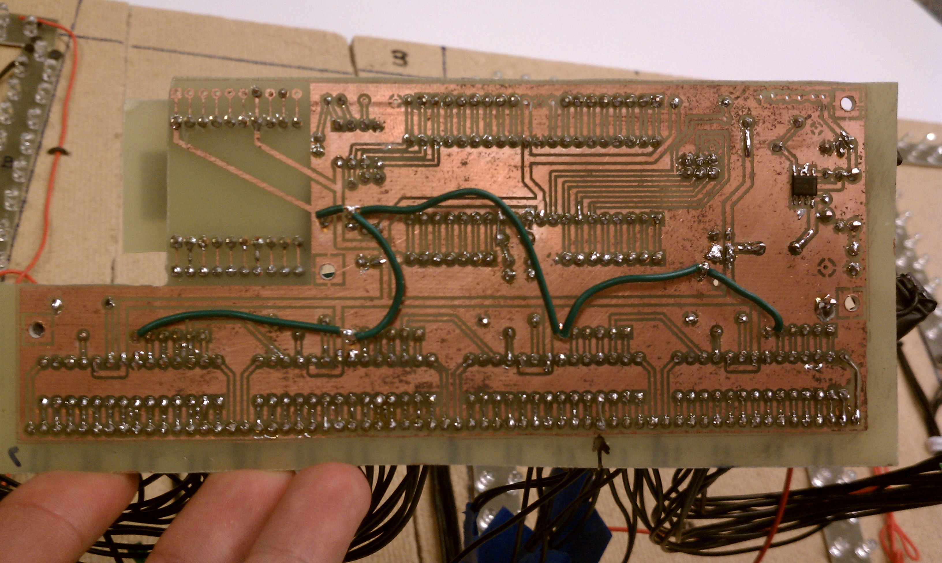
Target board with connections made.
Hardware Design
The electrical schematic for our design is shown below, with two sub-cells describing the connections of the display's two varieties of segments and the connections that the Bluetooth breakout board makes to the RN-42 module. From pictures you can see that with a single sided copper board and this compact layout, a lot of wiring must still be done by hand to connect the LED drivers (the daisy chained green wires). A larger board layout or double sided copper boards could decrease the amount of external wiring required. See the Appendix for a complete parts and budget listing.

Schematics diagram
Printed Circuit Boards
Introduction
The pace clock requires a large format display with several hundred LEDs. To purchase circuit boards that are the size of the digits (roughly 12”x6”) would be prohibitively expensive--several hundred dollars--since manufacturers calculate pricing based on area. Additionally, there is a lot of sparse area in the center of the 7-segment digits, which needs no circuitry. For this reason, we decided to make only the segments themselves as 5”x0.75” strips to wire the LEDs together and provide a flat surface to ensure that all LEDs point in the same direction. These strips are then wired with standard 22-gauge solid copper “lab wire”, and held to panels of sound insulation fiberboard with short carpet tacks, for easy repositioning and connection debugging.
Without the class’s budget restriction, we would still have fabricated the boards at home, but using complete FR4 panels that connect all the segments’ individual LEDs, wire their power supplies to a single source, and collect their 15 current sinks (14 half-segments plus 1 decimal point) into a single header. Then, connectorized ribbon cables could more easily connect each panel to the headers on the target board, where the 16-output LED drivers sit.
Paul designed and fabricated all the printed circuit boards at home over spring break, using about 162 square inches of single-sided copper-clad FR4, plus about half that for backup parts and to make a second display for a wireless time synchronization project.
Since this DIY fabrication method uses only single-sided boards, a lot of wiring must still be done by hand, considering the 6 signals required to communicate with the LED drivers and the fact that the circuit is non-planar. These connections were broken out to header pins and then wired with homemade jumper cables / wiring harnesses made from standard solid-core 22gauge wire and locking header pin connectors. These female header pins were found in a surplus bin for $0.05 each, since they lack the plastic housing into which they are intended to be inserted. Our tight budget precluded buying both the inserts and the SIP housing, so adjacent pins are shielded from touching by wrapping each female connector with electrical tape.

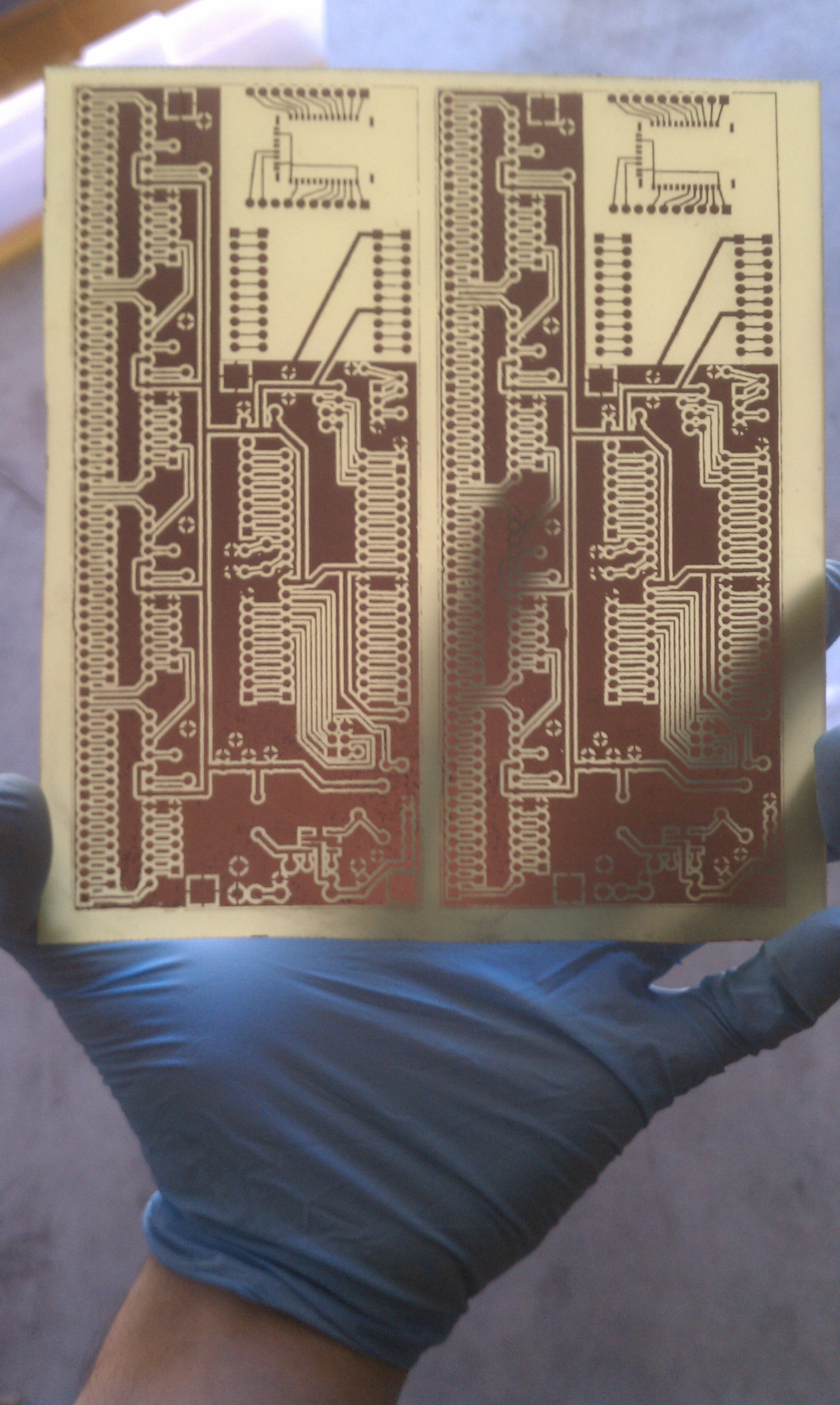
Two fabricated target boards.
Circuit Board Designs
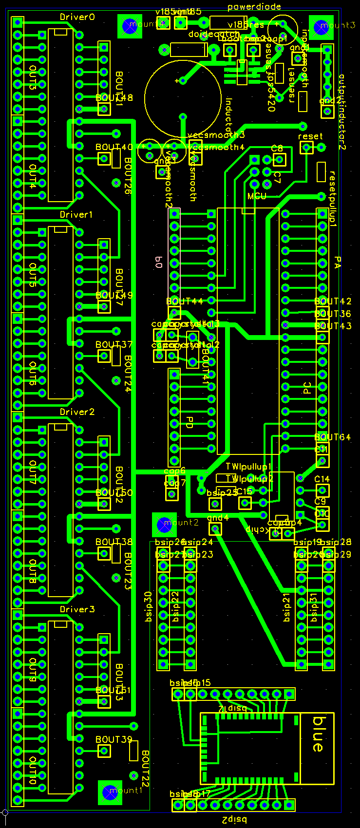
The first step to make custom printed circuit boards, whether you are fabricating them at home or sending your designs to a manufacturer, is to design your circuit schematic and lay it out using a PCB software package. Eagle PCB is a commonly used program, but the free version has maximum board size restrictions. Paul chose FreePCB instead; it has fewer features and lower reliability, but worked adequately for our purposes. FreePCB builds Gerber and drill files which can be sent to PCB manufacturers, used to make PCBs at home. Once satisfied with the design, Gerber files can be generated and viewed using this free online tool (http://circuitpeople.com/). From there Paul downloaded PNG files of the top-copper layer of the Gerber files, and printed them from Photoshop. Measuring the distance between two holes in the PCB layout software and comparing that to their separation distance in the printed design, Paul then rescaled the image in Photoshop--interpolating with high oversampling--to give the correct-size design in real printed pages. This method worked well, and there were no alignment problems at all.
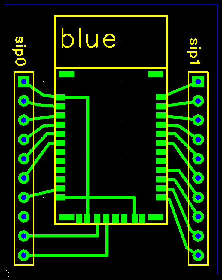
The circuit board designs Paul completed and fabricated are available for download or viewing below. The long segments are used as the segments of four digits. The short segments (several per strip) are used for the decimal points, the colon, and the hyphen. The RN-42 breakout board is used to expand the useful pins of the Bluetooth module to 0.1” header spacing. The target board is the main circuit board for all the electronics, including the regulator and its associated power components, the microcontroller and its connections to the peripheral integrated circuits, the 4 LED driver chips, the real-time clock chip, the Bluetooth module on its breakout board, and passives/wiring to connect all these subsystems.
There are several files available for download or viewing, including pre-scaled PDFs of the designs for DIY PCB makers, Gerber files for those who prefer to send their designs out, and screenshots of the designs from FreePCB. We will release the FreePCB layout files upon request, as well as the circuit schematic above, which was drawn using ExpressPCB’s schematic editor.

Stuffed PCB backside.
Note that the original RN-42 breakout module was not mirrored, a mistake Paul made in the design. To fix this, we have posted a version of the target board PDF with only the RN-42 breakout board (which must be mirrored before printing), as well as a PDF that has already been mirrored (and therefore should be printed directly). The original place on the target board where the RN-42 breakout board was drawn (the lower right corner) has been blanked out since it is a non-mirrored surface mount component on a through-hole board design. Interestingly, Paul did remember to mirror the connections of the regulator--the only other surface mount component—so the power circuitry works as intended. When making PCB boards on your own, visualize flipping your design ink-side down onto the copper, and verify that the mirroring is correct. As a general rule, an all-surface-mount design needs to be mirrored, and an all-through-hole design does not (mounting the sockets, etc. on the non-copper-clad side). The trick is making designs that incorporate both types. In retrospect, Paul expects this to be a mistake he will only make once; since this was his first time with homemade PCBs, it was a learning experience.
Since these boards were fabricated before figuring out which connections to make between the microcontroller and the bluetooth module, only the power and ground connections are made to the bluetooth module. The UART connections can be made with jumper wires between the breakout headers, with connections as shown in the circuit schematic. There are two other modifications to these boards to make them match the final schematic: the CLKOUT output of the PCF8563P (pin 7) should be connected to the microcontroller's D.0/INT0 (pin 14) on the ATmega32A, not D.7 (pin 21). This allows it to properly trigger the external interrupt INT0. The connection to D.7 can be broken before or after etching the copper, or it can be left alone if the code leaves D.7 as an input. Finally, we discovered that the CLKOUT output of the PCF8563 is only a current-sink, so a pull-up resistor is necessary just as on the TWI clock and data lines. Other people on online forums have had this problem because the NXP datasheet is not clear. The board already has a hole to insert one lead of the resistor to connect to the PCF8563P pin 7, but the resistor must share a hole with the other two pull-up resistors at its connection to Vcc, or else be tied there on top of the board.
DIY Printed Circuit Board Fabrication
Paul has made a set of instructions for DIY PCB fabrication, which can be downloaded
here.
Recommended Tools and Lab Equipment
The following were either useful or essential to complete the PCB fabrication and display construction.
| Item | Comment |
| Free PCB | For PCB Design (Eagle is only free for small boards) |
| Circuit People Gerber File Viewer | Excellent online tool with selectable size downloads |
| Photoshop or Other Image Editing Software | For image resampling, scaling, and printing |
| Drill Press | Holes can be drilled with sufficient accuracy by hand. |
| Circular Saw | For cutting the fiber board and/or other wood enclosure |
| Jigsaw with tile/glass abrasive blade | Required to cut FR4; or use a shear/guillotine. |
| Hobby/Exacto-Knife with sharp blade | Essential for fixing shorts/problems on patterend PCBs |
| Tungsten Carbide "Wire Size" Drill Bits | Drill Bit City #80 - #56 Gauge, retipped ones work great |
| Anhydrous Ferric Chloride | Cheap (ebay) and reusable (does not degrade) |
| Paper Towels, Newpapers, Cardboard | To clean up chemical tanks and any spills |
| Plastic Etch and Rinse Tanks/Containers | Should have flat bottoms to minimize liquid required |
| Nitrile Gloves | To protect you from the Ferric Chloride |
| Plastic tongs, hook, and/or mixing stick | Ferric chloride etches all metals, even stainless steel! |
| Scissors | To cut out the PCB design |
| Acetone | To clean PCBs before iron-on, and to remove toner after |
| Green Scotch-Brite Pad | For cleaning/abrading copper before ironing on |
| Window cleaner | To clean PCBs after scotch-brite, which leaves particles |
| Old Clothing Iron | Water removed, hottest setting, may get ink on it! |
| Glossy Magazines | Cheap, uncrinkled, non-recycled, glossy, thin paper |
| Samsung Laser Printer | Factory Brother ink and DIY refill inks do not work! |
| Wire Cutters and Strippers | Many PCB connections made on unprinted side |
| Soldering Iron and Lead Solder | ZD-929C from MPJA. 1/32" tip, plus 1/64" tip for RN-42 |
| Electrical Tape | For wrapping connections to the screen |
| Heatshrink and Heat Gun | (I didn't use these, but highly recommended over tape) |
| Solder Flux, Flux-Pen, or Paste | (I didn't use these, but would simplify RN-42 soldering) |
| A Good-Quality Digital Multimeter | Absolutely indispensible. Should have audio-out for low-R. |
Software
The Pace Clock
TimeSystem.c
This function is the main operating program that runs on the microcontroller in the pace clock. It handles parsing through the data memory, interpreting commands, updating the display, communicating with all the peripheral chips (except the regulator), and managing user interactions that arrive wirelessly over Bluetooth. The state of the clock can be one of several modes, corresponding fairly closely with the available instructions in the instruction set specified above. Flagging between the main program execution and the interrupt service routines acts as the main way that the user can advance to different modes, skip through intervals, pause the clock, and upload new data to the EEPROM. The most complicated part about writing the code for the microcontroller was handling user interactions that arrive ashynchronously, but must be interpretted and applied to the state of software system, which would otherwise only be changed at the data parsing rate. The program was designed to check for user pauses, upload requests, and power on/off requests at the maximum possible rate, and to enter the lengthy instruction and timing interval updating/parsing code only when necessary. This is necessary, in general, once per second, since pace clocks operate on a minutes:seconds time scale for the majority of their operating modes.
In normal operation, the 32Hz clockout output from the PCF8563P real-time clocking chip serves as an external interrupt which acts as a screen update "heartbeat" for timing intervals and parsing new data from the EEPROM. New instructions are parsed, and the display is updated for interactive modes such as the routine prompt instruction. The main execution halts in an infinite loop for these cases, escaping when the state of the clock has been changed in an ISR due to receiving a byte over Bluetooth, which is interpreted by the USART ISR. After advancing out of a particular instruction or finishing a timing interval, flags are set to indicate that another piece of data (one byte for instructions or two bytes for timing intervals) needs to be read from EEPROM memory and interpreted. During interval timing, when new data does not need to be parsed, the clock simply reads the minutes and seconds from the real-time clock/calendar chip and optionally performs subtraction for counting down, or no subtraction for counting up to correctly update the display buffer. A large part of the code requires converting between the data-encoding formats of the external chips (both the LED drivers and the real-time clocking chip) and the formats that are used internally in the microcontroller memory. A large number of auxiliary functions are defined to simplify these lengthy conversions, and make the code more compact. The interpretation of the instructions is necessarily complicated and lengthy because each instruction in the instruction set is designed to do something different from the others; there is only so much sharing of code that can be done to minimize its expanse.
During normal parsing operation, the external interrupt ISR sends the newly updated display buffer to the LED drivers, at a rate of execution which is timed by the persistent 32Hz clock rate applied by the PCF8563P chip to the microcontroller external interrupt pin INT0. The exception to this is the millisecond timer mode, which must be timed using the on-board crystal because the PCF8563P uses a 32.768kHz crystal, whose period is not an integer divisor of 10 milliseconds. In this mode, the external interrupt is disabled, and a 8-bit counter/timer compare-match interrupt internal to the microcontroller is activated to accurately time 10 millisecond interval steps and update the screen.
The software implements a low-power sleep mode with the screen turned off when the user pushes the power button. However, the Bluetooth chip, the regulator, and the clocking chip remain on during this time. In spite of this, the power consumption is expected to be much less than with even a handful of segments illuminated on the display.
Parsing of the instructions and time intervals read from memory is handled in a large switch statement, whose cases implement the functionality specified in the instruction set. For example, the Set Clock instruction, when encountered, flashes the hours, prompting for the user to cycle through to the desired hour. After the user hits Enter, the infinite hours-blinking loop escapes, and program execution enters an infinite minutes-blinking loop so the user can specify the minutes. After escaping this, the values are written to the clock chip to keep accurate time, and parsing continues with the next data index.
The USART ISR decodes the 6 button presses available to the user on the Remote Control tab of the Android app, and calls button-press-handlers. Depending on the state of the pace clock, these handlers either perform no action or changes the clock state as described in the state transition matrix included above in the Design Overview section. Since most button presses are handled with simple "flag-setters" they can be decoded extremely quickly, and we do not have problems with missing interrupts from either the user interaction or the external interrupt from the clocking chip. The main program execution reads these flags and acts accordingly to advance the execution, pause it, parse backwards, etc. Since the ISRs are kept very compact, keeps the button presses are very responsive from a user's perspective.
The exception to the above is the Upload mode, which goes into a fast data-buffering state to record all the bytes received over the UART from the Bluetooth module. This is necessary because the 1024kB data is burst transmitted from the smartphone and we want to keep the upload time to a minimum. A software watchdog timer checks for a timeout condition if the upload is incomplete or interrupted so the pace clock doesn't break down if the uploaded data is incorrect or incomplete. After successful uploading, the uploaded data is written to the EEPROM, the state and parsing variables are reset, and the clock begins executing the instructions and data in its new program/data memory.
clockInterface.h
Specifies macros for all the available registers that can be read or set in the PCF8563P, as well as global configuration settings for its clock output frequency.
clockInterface.c
Initializes the PCF8563P real-time clock/calendar chip settings. Specifies a single function using Peter Fleury's TWI library to either read or write a register in the peripheral PCF8563P chip.
LEDinterface.h
Specifies the port for the SPI communication to the LED controllers and pin definitions for the six connections to the LED controllers.
LEDinterface.c
Specifies a lookup table to turn the numbers and the selected group of letters displayable with the 7-segment screen into one-hot encoding for the seven segments and the period of each panel. Initializes the SPI output, sends dot-correction data once at startup, and sets the communication speed. Uses a 96-Byte brightness value vector, which is selectively null-ed to write different values to the screen. Has a function to send a vector of bytes out the SPI port to the daisy-chain of LED controllers, latches the data, and sets the TLC5940 drivers to DC illumination. Has a function to take in a vector of four digits to display on the four panels, a byte for the colon, decimal places, and a display options character to format the 96-byte long buffer. Fosc/2 SPI clock rate.
twimaster.c
Peter Fleury's TWI library used without modification. See references section at the bottom of this page. 400kHz TWI clock used.
uart_mega32.c
Modified from the provided UART driver for the class to work on an ATmega32.
eeprom_data.h
Specifies macros to encode the bytes for particular instructions that are interpreted by the microcontroller in the pace clock, and initializes a EEPROM vector the size of the capacity of the microcontroller with a sample set of instructions for debugging. Also provides two functions to easily get a byte from EEPROM and to write a byte to EEPROM at particular indices.
The Mobile Application
The mobile application aspect of this project provides a novel way for the user to interact with the pace clock. Conventional (and very expensive) pace clocks either lack in configurability, or ease of use, or even both. The mobile application gives the user a cost-effective and time-efficient way to easily configure the pace clock remotely while providing the user with a much better picture of the contents of each individual routine. The user is able to control the pace clock with a mobile application written in Java and the Android SDK. Named TimeSystem, the application interacts with the pace clock by transmitting data via Bluetooth connection. TimeSystem consists of two tabs: Remote Control and Routine Configuration. The Remote Control tab provides the user with a familiar interface to send commands, while the Routine Configuration tab allows the user to build the desired training routines with an easy-to-use GUI. The application stores a private SQLite database of all 32 fully configurable routines and compiles the database into a 1024Byte file for upload to the EEPROM.
Overall Design
For the user's convenience, the application should consist of intuitive interfaces for the following features:
1. Scanning of Bluetooth devices in range
2. Pairing request for unpaired devices
3. Establishing RFCOMM channel/socket and device connection
4. Transmitting simple "remote control" command bytes
5. Configuring and storing 32 routines with timing events and all instructions
6. Compiling the 1024Byte file to upload to the EEPROM
Remote Control
The Remote Control tab is the first screen that appears when the user first launches the application. If Bluetooth is not enabled on the user’s device, then a dialog will appear asking for the user’s permission to enable Bluetooth. If the user denies the request, then a small notification will say that Bluetooth connectivity is required to interact with the pace clock. By design, the application does not require a Bluetooth connection to perform other functions such as the configuration of individual routines. Once the user enables Bluetooth on the mobile device, the user can touch the hardware “Menu” button that exists on all Android phones to bring up the Bluetooth connectivity options menu. The “connect a device” menu option allows the user to connect to the clock, or other Bluetooth-enabled devices for testing purposes. The “Make discoverable” option makes the user’s mobile device discoverable to other Bluetooth-enabled devices. Generally, the “Make discoverable” feature is not used except in application or device testing.
In the devices menu, the user can also scan for not-yet-paired devices. By touching the desired device, the application will attempt to establish a connection with the selected device. Once a connection with the pace clock is established, the device name for the clock will appear on the top right corner of the screen. At this point, the user is able to interact with the clock by using the buttons on the Remote Control tab. Touching each of the buttons sends a byte of instruction to the clock, and the expected behavior of the clock when each button is touched at different states is outlined in the User Interface State Machine above. However, note that the Upload button behaves differently from the rest of the buttons. Once the Upload button is touched, a dialog asks the user for upload confirmation. After the user touches the OK button, the application sends an upload instruction byte to the clock, waits for a second to ensure that the clock is in upload mode, and prepares the 1KB file for upload.
Routine Configuration
The Routine Configuration tab displays the list of 32 configurable routines to the user. Upon selection of a specific routine, the content of the routine is brought forward to allow user configuration. The user touches the hardware Menu button to bring up two event options:
Add timing event:A timing event serves as the core of each routine. The user can select the desired time interval in minutes and seconds using a custom time picker and indicates whether the clock should count up or down using radio buttons. The user is also able to insert a training message that will be displayed alongside the instruction. Finally, the user can touch the Add button to insert the instruction.
Add an instruction: A list of instructions for the clock is displayed to the user when this option is selected, and the user is able to select the desired instruction to add to the current routine. The instructions Loop and Jump require further user input. More specifically, when the Loop instruction is selected, the application prompts the user for the desired number of loops, whether the clock should display the number of loops remaining, and whether the current loop to insert is an inner loop. When the Jump instruction is selected, the application prompts the user for the routine number to jump to.
All new instructions are added to the end of the current routine. It is up to the user to move each instruction to the desired location within the routine. The user can choose to have each instruction moved up, moved down, or deleted from the current routine by simply touching the instruction. However, the user must make sure that the headers and footers of the loops are in correct order. More specifically, each loop must be properly enclosed by a loop footer and no loop, outer or inner, can exist within an inner loop. To better differentiate the loop headers and footers from the rest of the instructions, outer loop headers and footers are colored green while inner loop headers and footers are colored cyan. Additionally, the user may choose to edit a timing event by long-pressing any existing timing event in the routine.
Screenshots


Left: Bluetooth Request prompt. Right: Remote Control tab with the six command buttons.


Left: Touching the hardware Menu button brings up the Bluetooth connectivity options menu. Right: Device connection dialog.


Left: Routine Configuration tab with 32 configurable routines. Right: Sample routine with options menu brought up by user touching hardware Menu button.


Left: Interface to add timing events. Right: Interface to add instructions with a list of instructions that can be added.


Left: Loop addition interface. Right: Interface to edit instruction event order and deletion.
Results top
The pace clocked works very well, and the wireless control from the smartphone is very low latency and functionally correct. The routine configuration tab in the Android software is full featured and implements all the instructions we originally included in our project proposal. The remote control tab works as intended and is easy to use with its oversized buttons. The pace clock correctly parses all the instructions and we have iterated on the basic design to give the most informative and intuitive behavior when counting through intervals, looping, setting the clock, powering on and off, etc.
Video demonstration of Android control over Bluetooth.
We modified and improved some of the instructions behavior in slight ways, compared to the project proposal. For example, the scheduled start time is no longer encoded in the data memory since then the user would have to re-upload the whole page file to account for delays or day to day scheduling of a routine's start time. Instead, the user is prompted to enter the scheduled start time just as they are to set the clock in the clock setting mode. Skipping through and pausing/resuming timing intervals works as it should, as do all the loop instructions, the jump instructions, the selection modes, the uploader, and the power button. The Android routine configuration tab correctly converts the user's selections into the machine code that is sent to the microcontroller during an upload operation.
There is one undesirable behavior which we believe is caused by the RN-42 Bluetooth module during connection. That is that the first few connection attempts from the smartphone to the Bluetooth module do not succeed. This occurs most notably when we have been controlling the pace clock from one smartphone, and we want to switch to controlling it from another. The RN-42 stores a table of 8 paired devices in a FIFO list, and we believe this problem is just that the Android Bluetooth drivers have a connection-attempt timeout which is shorter than the processing time for the RN-42 to recognize and connect to a different device. Fortunately, this is not a problem after the first connection is made, and connection attempts succeed on the first try after quitting the app (which closes its Bluetooth session by design of the Android operating system) and re-opening it. Furthermore, our app makes it easy to retry the connection with only 2 or 3 taps, since the Bluetooth connection list is available directly from the remote control app. From personal experience, we believe this slowness in hopping between connected devices is common in all low-complexity Bluetooth modules, as it has been an issue with a Motorola hands-free audio device when switching its connection from one cell phone to another.
The method of wiring all the segments by hand is cumbersome, and stresses on the joint between the wire and the PC board (from carrying it around for weeks for this project) occasionally broke connections that needed to be repaired. A package and mounting scheme that is more robust than our kludgey fiberboard and plywood system would drastically improve this, as would monolithic integration of several segments and perhaps the LED drivers on a single printed circuit board. For reconfigurability and ease of performing repairs in this prototype pace clock, the segments are carpet-tacked to sound insulation fiberboard; they would be more securely attached in a real product.
The most satisfying part of this project is pausing and resuming the millisecond timer. Because we disable it by nulling a single ISR mask bit in the microcontroller code, and because the Bluetooth communication is very fast, the result is so low latency that it feels almost like you are controlling a handheld stopwatch! Its actually even better than that, because the buttons on some handheld stopwatches are notoriously bad, and the smartphone touchscreen is so responsive. You can see some of this in the video we have posted. Although the video doesn't do the screen justice (it's really really bright!), the screen looks great, the 100-millisecond steps appear perfectly timed, and the 10-millisecond digit is too fast for the human eye to decipher. There is absolutely no skipping, halting, or stuttering, and there are no problems with missed button presses. Late in the debugging stage, we noticed some glitching of the display segments when running the millisecond timer, but we believe the problem was that the SPI connection to the LED drivers is shared with the STK-500 programmer connection, and that was causing some display glitches. After removing the ribbon cable used to program the microcontroller from the STK-500, the glitching appears to be fixed. We knew from class that problems programming could be attributed to other SPI circuits in your embedded design. This however, was the opposite case: the STK-500 connection was causing problems with our SPI data transmission when we were not programming the microcontroller over it.
All of the above successes are the result of many hours of [coding, debugging, testing] repeatedly.
Conclusions
Summary
The greatest impact of our project is that it brings high-functionality wirelessly programmable pace clocks into a price range that small swim teams, local pools, and even individual athletes can afford while simultaneously enhancing the user interface with intuitive, ubiquitous Bluetooth smartphone control. To our knowledge, a pace clock with this level of cross-platform integration (supported by open source instruction compilation and wireless interface commands) does not yet exist in today's marketplace. Compared to the sleekness of smartphone control, existing pace clock systems use specialized proprietary programmers with physical buttons, tiny alphanumeric LCD screens, and larger packages.
Buying only small quantities of the required parts, we were able to build a prototype wireless programmable pace clock for nearly an order of magnitude lower cost than the commercially available Colorado Time Systems clocks. This comparison is not completely fair, since their systems are much more polished, have more features, include technical support, operate with a suite of other products, and are made by people with nonzero labor costs (unlike ECE students). With scaled up production, even greater savings could be achieved, or profit for us if we sell these clocks at a fraction of the price of the current commercially available systems.
Additionally, the simplified, open-source format of our instruction set means that any electronic device can control (or program, if sufficiently sophisticated) the pace clock. Drivers can be written to adapt control to any software program that a coach likes to write workouts in, including Excel and the commercial HyTek meet manager software. By moving the workout design and programming method into software (with mouse clicks or touch screens rather than physically actuated buttons), it can be made easier and more intuitive to use, as well as allow a wider range of computing media to interact with the pace clock.
Ethical Considerations
With reference to the IEEE code of ethics, we strove to complete this project working in an ethical manner, and to ensure that the finished project does not violate any ethical considerations. In particular, we have assisted colleagues (several other groups) working on similar projects as well as completely unrelated projects. We have had friendly interaction with our professor and with other students that were professional, respectful, and beneficial to our project and, hopefully, to theirs. We have reported our results accurately, making only realistic truthful claims about our successes, and acknowledging our mistakes. We have sought and accepted criticism in the design of this project, and cited the sources of other people's code that we used (all with permission). We have referenced the companies whose products are similar to our project, reviewed their patents, and explained why we believe we are not infringing on any of their intellectual property in the design of our pace clock.
We have also offered to provide our experience, time, and circuit boards to help other people add Bluetooth control or communication to their designs. We have engaged in discussion and explanation of the projects being undertaken by our classmates, and both provided and received suggestions about how the projects could best apply microcontroller technology to realize embedded systems that maximize their potential and impact. The IEEE code of ethics also makes references to the engineering decisions we make to design electrical systems, and how their design, misuse, or impact should be consistent with “the safety and welfare of the public” and not expose others or their property to damage. For safety and usability considerations such as these, please refer to the safety section of this website.
During the Android application development process, some sample source code and tutorials were consulted. Copyright disclaimers can be found in the project source code. The README file in the project also contains a breakdown of the sources used. The references mainly consists of material from Google's Android Open Source Project and a tutorial by Josh Clemm, both of which can be found in the References section.
Safety and Usability
There are some safety considerations with having an electronic system close to a pool. There are a number of mitigating factors related to this concern. Many manufacturers adopt administrative control—the clock must not be placed near the pool; for example, it could be mounted on a wall rather than sit on the pool deck. The commercially available pace clocks are splash resistant but not waterproof. Adding a plexiglass font panel (beyond our budget) would make it almost as splashproof, and a full enclosure would bring it to the level of commercially available systems. This type of timing system is not intended to be submerged in the water; electrical shorts would occur and it would damage the integrated circuits. Other systems use batteries to avoid tripping on a cord extending to the wall outlet, although that certainly complicates electronic measures if the system does fall into the pool with high capacity batteries. Pool water is fairly conductive, so all electronics would quickly be shorted within very short distances if the unit did fall into the water. We are not using batteries for this system, so a knot limiting the length of the power supply cord can be placed to ensure that the pace clock becomes unplugged from either the wall or its rear DC power connector before the unit comes within reach of the pool edge.
Our project is not intended to be used by people with special needs such as blindness or a physical/mental disability which prevents them from pushing buttons on a remote control or seeing the LED display. The system is very easy to use, and simplified graphical interfaces on the Android workout configuration tab and the remote control tab allow even computer illiterate users to easily design a workout and upload it to the pace clock. Simplified controllers that do not implement the configuration or uploading functionality are a possible future addition.
Another safety concern is with regard to epileptic users and the fact that 3-4% of epileptic people may have a seizure triggered by strobe lights flashing in the range of 15-20Hz. (
source). In recognition of this issue, we have designed our “rave mode” screen demonstration conservatively, and present below a number of mitigating factors to explain why the screen should not cause problems for people with photosensitive epilepsy.
There are a variety of mitigating factors related to this concern. Our system never updates the screen faster than 4Hz except during the millisecond-timer mode, which counts upwards at 100Hz (counting 10-millisecond intervals), so the common trigger range is avoided. Furthermore, the fact that numbers are being counted means that not all of the digits are being changed simultaneously, and the pattern of illuminated segments is not a strict on/off strobe effect, but instead it is a rearrangement of the illuminated segments. Distance is also a mitigating factor, since with a wall-mounted pace clock, users will be at least 10 feet from the clock and it will occupy only the periphery or a small fraction of their vision in most cases. Additionally, since the display is fairly directional, a photosensitive epileptic sufferer will not be subjected to strong illumination simply by being in the same room (as with the ultra high brightness of a strobe light, which can illuminate an entire room). Finally, and perhaps most importantly, the changing digits represent only a fraction of the total light intensity, which is the main concern for photosensitive epilepsy—that is, out of all the illuminated LEDs, only a few segments switch on or off at each cycle, so the variation in light intensity is not like a strobe light (strong on/strong off), but rather a small fluctuation of total light intensity as more or fewer segments are illuminated.
The radio frequency radiation of our design is addressed in the legal consideration section below.
Legal Considerations and the FCC
Our project will plug into a wall outlet, but all power safety standards are already handled by the laptop power brick we are recycling from a broken HP laptop. Power bricks provide isolation through transformers and a rectifying bridge, ensuring that we cannot damage electrical systems (or feed power back into the grid) by making electrical wiring mistakes on the DC output end of the power brick. The inputs and outputs are current-limited. This is essentially just as safe as using the 9v power supplies that we do for the STK500 and target boards. The only difference is that our power supply runs at 18.5v to provide sufficient overhead to drive 9 LEDs in series between the power rail and ground.
We have used a DC/DC switched buck regulator to use the 18.5v power supply to power our 3.3v electronics. This regulator switches at 500kHz, and is reported by Texas Instruments to be within the FCC’s limit for allowable radiation at that frequency. The FCC regulates RF power radiation at frequencies above 9kHz. A measurement system is not available in the lab to confirm this, but since the trace length between the regulator and its inductive/capacitive smoothing filter were minimized (less than an inch on the circuit board), and the signals were confirmed to have mostly DC content after smoothing, we believe that the radiated power from the regulator and power circuitry is insignificant—it certainly does not cause problems with our Bluetooth radio link, which operates at a higher band.
The Bluetooth module we used operates in the 2.4 GHz Industrial, Scientific, and Medical (ISM) Band, and is governed by Part 18 of the FCC rules. The device is a Class-2 Bluetooth module, with a maximum transmit-power of 4dBm, lower than the cutoff for it being labeled as a Class-1 device. The Bluetooth module we used in our circuit, as well as any Bluetooth module included in our US-legal HTC smartphones, are licensed devices and guaranteed by the manufacturer to comply with the FCC maximum power regulations, frequency hopping standards, and interference specifications. Even with improper inputs, the Bluetooth module cannot violate the FCC interference and power limits, and it effectively serves as a transparent link between the phone’s application and the microcontroller’s received data from its USART hardware. The total radiated power from our Bluetooth module is on the order of 0-4dBm, which is an order of magnitude less than the maximum permissible radiated power of a cell phone (33dBm), so we do not expect human radiation absorption to be an issue with our design. Furthermore, humans will not be very near to the pace clock, and the phone will be held an arm’s length away from the user when using its buttons (not near the brain, as it is with cell phone conversations), so there is no significant RF radiation concern with our design.